
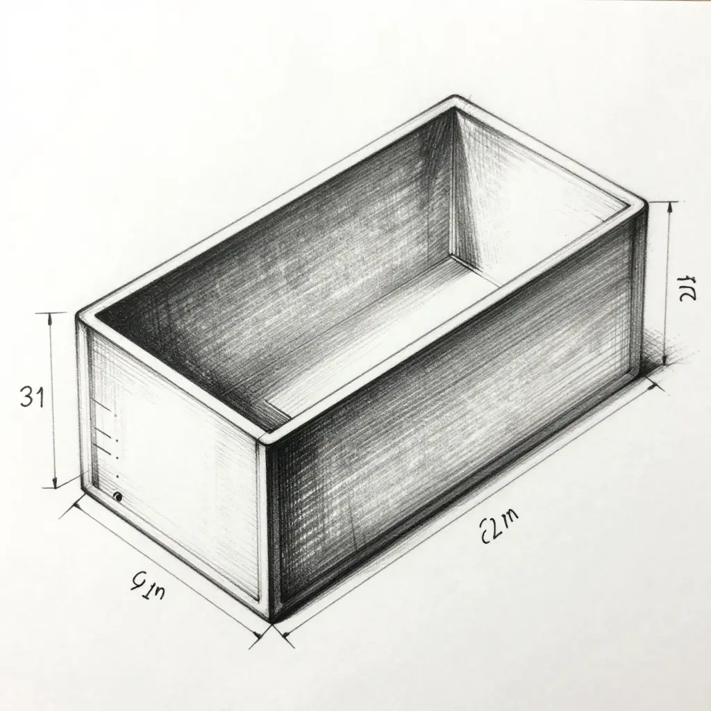
Mold Draft Angle Fundamentals in a Bagasse Clamshell Box
Every custom bagasse clamshell box is shaped by the physics of wet fiber long before it reaches a customer. The number that decides most of the outcome is the draft angle: the slight taper on each vertical wall that lets the molded part leave the tool without tearing. Miss it and the part grips the mold, so the cost turns up as scrap, slow cycles, and wasted pulp.
What the Draft Angle Actually Is
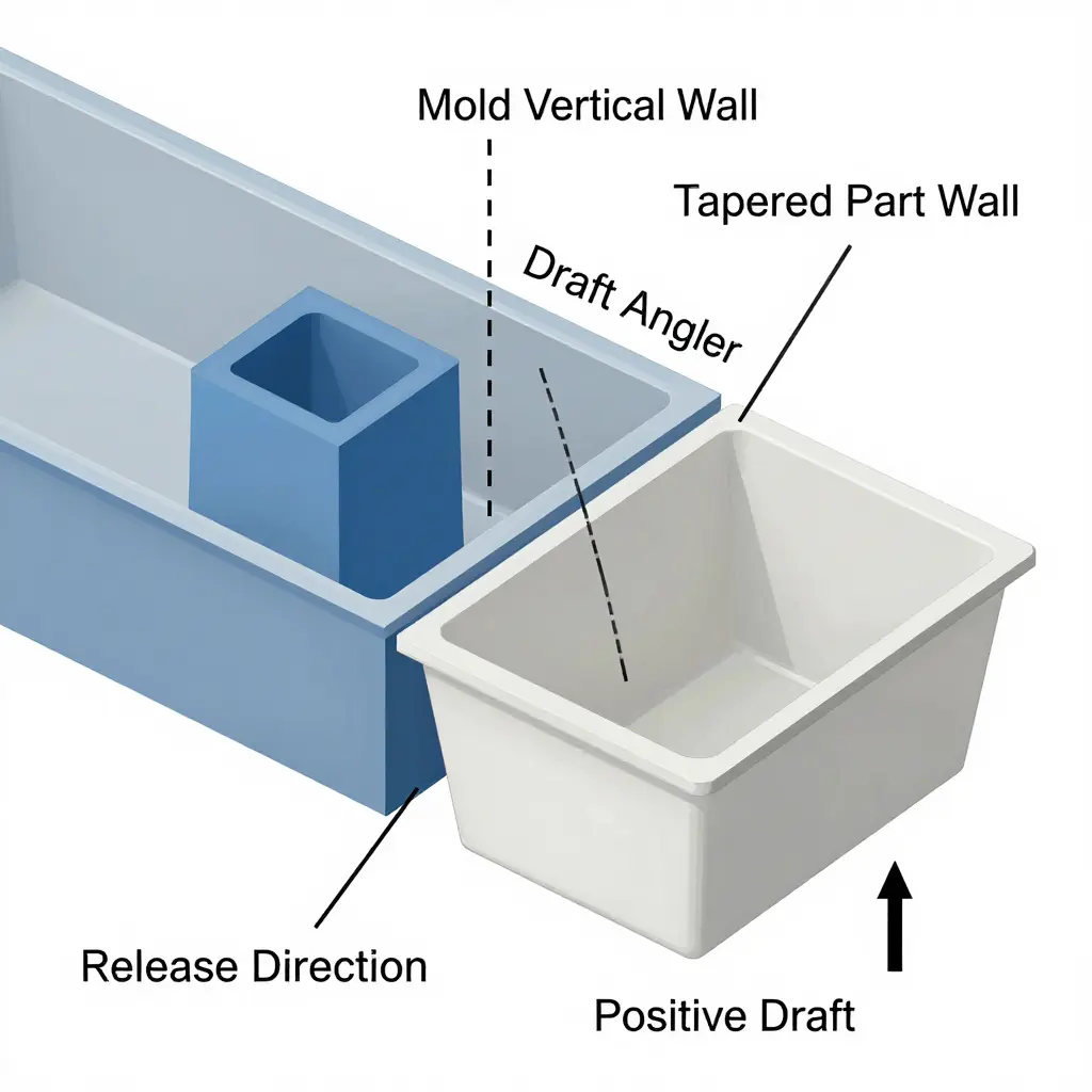
In a molded fiber (pressed pulp) tool, cavity and core walls are not vertical. Each one leans a few degrees off the direction of pull, and that lean is the draft angle. When engineers talk about the bagasse clamshell box draft angle, they mean how far the box’s side walls taper away from the mold’s vertical axis.
Why Molded Fiber Demands a Positive Release Angle
A bagasse part is a porous, fibrous shell formed from a water slurry, not a smooth injection-molded plastic. As it presses and dries it shrinks onto the tool surface, and the fiber grips the metal. Positive draft turns that grip into a slide. At zero or negative draft the part locks in place, and the vacuum that formed the tray keeps pulling against removal.
How the Angle Is Measured
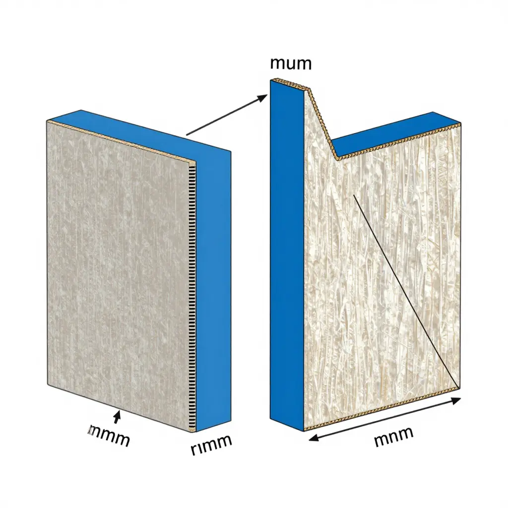
Draft is the angle between the mold’s reference vertical wall — the direction of pull — and the sloped wall of the cavity or core. A toolmaker draws a vertical line and reads the arc between it and the tapered surface. Typical molded fiber parts run roughly 2 degrees to 5 degrees per side; deep clamshell trays often need more.
Factors That Change the Required Draft Angle
No single angle fits every job. These variables push the required draft up or down:
- Fiber slurry thickness and consistency – thicker, wetter pulp builds heavier walls that grip the mold harder, so it needs more draft.
- Wall relief depth – deeper trays and taller side walls create more sliding contact; depth and draft rise together.
- Surface texture and embossing – rough or deeply embossed walls interlock mechanically with the tool and need a larger release angle.
- Mold material and surface finish – a polished aluminum or stainless tool releases more easily than a rough or worn one, so it can run a smaller angle.
- Demolding method – air-assisted ejection and vacuum release tolerate less draft, while mechanical stripping usually needs more.
- Corner radius and geometry – tight, sharp corners concentrate fiber compression and need extra draft to keep the fiber from pinching.
- Part shrinkage during drying – higher shrink rates tighten the shell onto the core, which raises the angle needed for a clean release.
When There Is Too Little Draft
Too little draft is the most expensive mistake in molded fiber tooling. The part sticks, fibers pull out of the surface, and side walls tear or delaminate when they are forced free. Operators scrap trays, and cycle time climbs while ejection turns into a fight. A bagasse clamshell lunch box supplier worth using will have drafted the tool correctly from the start.
When There Is Too Much Draft
Generous draft fixes release and creates other costs. Steeply tapered walls consume extra pulp slurry, so material cost rises with every unit. The same footprint now holds less volume, which shrinks the usable interior space. Steep walls are also weaker: they flex more under load, and the box loses the rigidity that keeps it from collapsing.
The Bottom Line
Draft angle balances easy release against material efficiency. The design problem in a bagasse clamshell box is to find the smallest positive angle that still demolds cleanly every cycle.
Draft Angle vs. Corner Wall Thickness: A Design Trade-Off Table
When you commission custom molded-fiber clamshell box tooling, two variables dominate the conversation between product designer and mold engineer: the draft angle cut into every vertical face, and the wall thickness carried through the corners. Change one and the other usually needs a correction. The table below maps the common trade-offs.
| Design Variable | Typical Range | Primary Benefit | Primary Penalty | Impact on Ejection / Release | Impact on Structural Rigidity |
|---|---|---|---|---|---|
| Draft angle – minimal | 0.5 to 1 degree | Tight vertical profile and compact pack footprint | High sliding friction, scuffing, and cosmetic marks | Hard release, needs ejector pins or air assist | No direct contribution to rigidity |
| Draft angle – standard | 1 to 3 degrees | Balanced release force and clean surface finish | Slightly taller nested stacks | Smooth, low-force ejection | Negligible effect |
| Draft angle – steep | 3 to 5 degrees | Fast, damage-free demolding and shorter cycle time | Reduced usable volume and loose lid fit | Excellent release, minimal resistance | Minor gain from thicker base corners |
| Corner wall thickness – thin | 0.8 to 1.2 mm | Material savings, lower unit cost, faster cooling | Weak corners, flex, and leak-through risk | Distortion and pin push-through during ejection | Low rigidity, prone to buckling and cracking |
| Corner wall thickness – standard | 1.2 to 1.8 mm | Good balance of rigidity and fiber economy | Moderate material consumption | Stable, predictable release | Solid structural integrity |
| Corner wall thickness – thick | 1.8 to 2.5 mm | High rigidity and better heat retention | Longer cooling, sink marks, and warpage | Heavier part and higher ejection force | High rigidity and load-bearing corners |
| Corner fillet radius (inner / outer) | 1 to 3 mm / 2 to 5 mm | Even stress distribution and smoother fiber flow | Added tooling complexity and cost | Easier release right at the corners | Improves rigidity and resists corner cracking |
| Thickness-to-draft ratio (pairing) | 1.0 to 1.5 mm per degree | Optimized wall-to-angle match | Poor pairing causes shorts or flash | Balanced, repeatable ejection | Balanced rigidity across the whole box |
Widening the draft angle changes how the wall meets the corner, and thickening that corner changes how the part releases, so the two have to be tuned together rather than one at a time.
Corner Wall Thickness Fundamentals in Molded Fiber Clamshells
In a custom bagasse clamshell box, corner wall thickness is more than a cosmetic detail. It records how fiber, water, and pressure behaved inside the mold during forming and pressing. A corner sits where three surfaces meet – side walls, floor, and base – so it behaves differently from a flat panel, and that behavior sets rigidity, stacking strength, and seal integrity in any disposable lunch box format.
How material distributes during pressing
Bagasse clamshells are formed from an aqueous fiber slurry drawn onto a screen by vacuum. Fiber deposits fastest where the mesh is open and the flow is unobstructed, and slowest in deep recesses where fluid has farther to travel. When the matched molded fiber tooling closes, it compresses the wet mat, squeezes out water, and consolidates fiber against the heated die. Corners are usually the deepest and most confined features in the geometry, so the local pressure gradient there is steep.
Why corners thin or thicken
A corner thins when fiber cannot migrate into the recess before the mat sets. Sharp internal radii, steep draw, or an abrupt horizontal-to-vertical transition starve it and leave lower local fiber density. It thickens when the geometry traps fiber or the press cannot fully consolidate the mat – often at generous radii, or where two forming surfaces meet and hold excess material.
Fiber migration is the mechanism
Corner wall thickness and fiber migration are the same story. Fiber has to flow laterally along the mat to fill a corner, and the easier that flow, the more uniform the wall. Restricted migration produces thin, brittle corners with a dense skin. Excessive migration pools fiber and leaves thick, under-dried corners that press unevenly. Molded fiber tooling design – radius, draft angle, and screen placement – sets those limits before a single box is produced.
Effects on rigidity, stacking, and sealing
Wall thickness sets the section modulus at the corner. A slightly thicker, well-consolidated corner resists buckling and passes vertical load into the walls, which is what makes stacking strength possible. Corners also carry the hinge and the sealing rim, so thickness there controls how the lid flexes, closes, and locks.
The cost of extremes
Thin corners crack, leak, and leave weak hinge zones. Overly thick corners lengthen cycle time, promote warping, and raise material cost. What you want is a controlled, uniform corner, not the thinnest or thickest wall you can achieve.
Key takeaways
- Corner wall thickness reflects fiber migration and pressure distribution, not only mold dimensions.
- Well-consolidated corners carry rigidity, stacking strength, and reliable sealing.
- Thin corners crack and leak; thick corners slow cycles, warp, and cost more.
How Mold Draft Angle and Corner Wall Thickness Interact
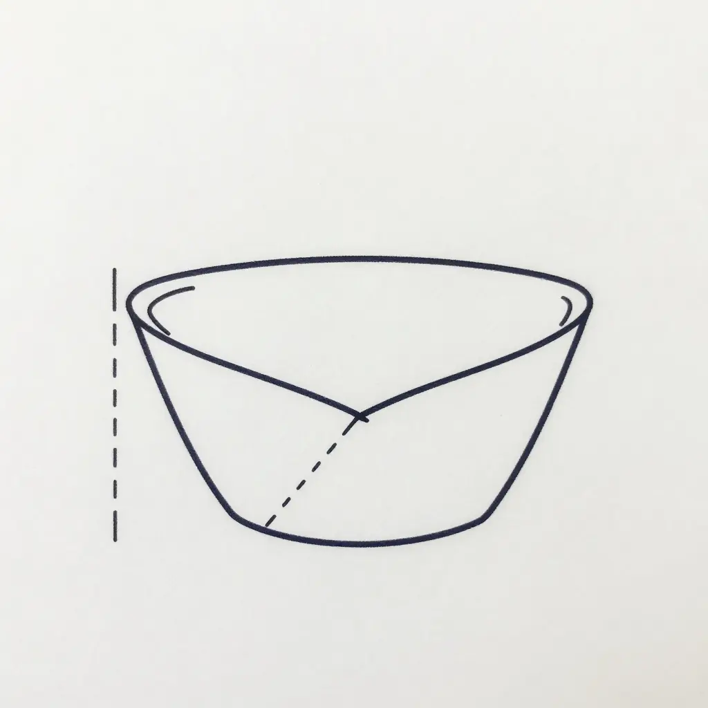
In molded-fiber production, mold draft angle and corner wall thickness are coupled, not independent. Both describe the same corner where the base, wall, and radius of a bagasse clamshell box meet, so a change to one forces a compensating change in the other. Here is the mechanics, and what each adjustment costs a B2B buyer.
The Mechanics of the Coupling
Mold draft angle is the taper on every vertical wall that lets the formed part slide off the tool. A steeper angle lowers the normal force against the tool and cuts sliding friction, so the part releases cleanly and ejection is faster. The penalty lands at the corner: a steeper wall stretches the fiber mat farther across the radius, thinning the corner and sometimes leaving a weak, translucent spot.
Corner wall thickness pushes the other way. A thicker corner adds rigidity, resists crushing in stacked shipping, and holds heat better. It also presses harder against the tool as the part cools and shrinks onto the core, so radial friction climbs. To avoid scuffing, that geometry then needs a larger draft angle to eject.
So more draft aids release and thins the corner, which means adding material back; more corner thickness adds strength and demands more draft. No decision moves just one of the two numbers.
A Representative Worked Example
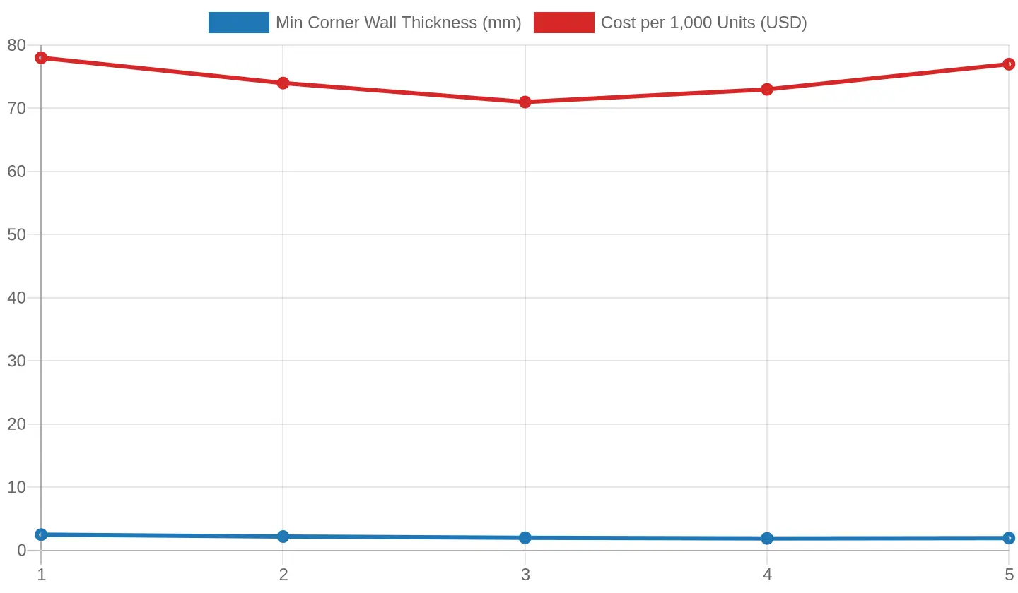
Consider a single-compartment bagasse clamshell box with a 12 mm corner radius. At a 1 degree draft the corner must be built to 2.5 mm to survive ejection without scuffing. Pushing to a 3 degree draft lets the corner drop to 2.0 mm while still releasing cleanly, because friction is lower. Going further to a 5 degree draft thins the corner enough that 0.2 mm has to be added back, which cancels the savings and reintroduces scrap.
| Draft Angle | Min Corner Wall | Cycle Time | Scrap Rate | Cost / 1,000 Units |
|---|---|---|---|---|
| 1 degree | 2.5 mm | 42 s | 6% | USD 78 |
| 2 degrees | 2.2 mm | 38 s | 4% | USD 74 |
| 3 degrees | 2.0 mm | 35 s | 3% | USD 71 |
| 4 degrees | 1.9 mm | 34 s | 5% | USD 73 |
| 5 degrees | 1.95 mm | 36 s | 7% | USD 77 |
The table and the chart below put the lowest unit cost near a 3 degree draft, at neither extreme.
What the Coupling Does to Buyer Metrics
- Cycle time: Higher draft angles eject faster and trim a few seconds per shot, but excessive corner thinning slows cooling and adds inspection time.
- Material consumption and part weight: Thicker corners consume more pulp per unit and raise part weight; thin corners save material but risk weak rejects that waste a whole part.
- Nesting efficiency: Steeper draft increases the stacking footprint and reduces how tightly the boxes nest, so fewer units fit per pallet and freight cost per unit rises.
- Cost per unit: The sweet spot balances tool wear, scrap, material, and freight. It usually sits mid-range, which is where most custom paper boxes are tooled for repeatable output.
For procurement managers the instruction is direct: specify draft and corner thickness as a pair, quote them against total cost per delivered unit, and validate the geometry on a pilot tool before committing to volume.
How Draft Angle and Corner Wall Thickness Shape Ejection Force
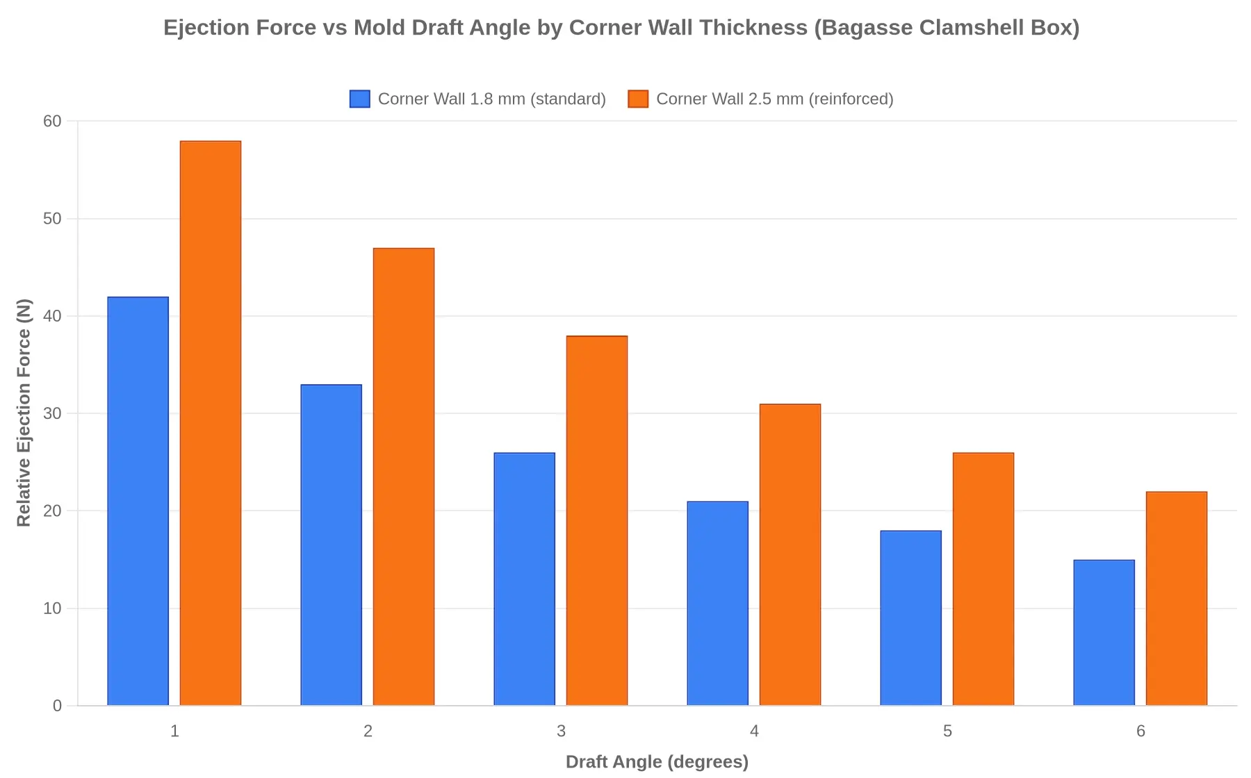
When a bagasse clamshell box is press-formed, the molded pulp is not the hard part – getting the finished part out of the heated tool is. Each degree of draft you build into the cavity geometry reduces the friction, suction, and mechanical interlock that hold the part back. Draft never acts alone, though. Corner wall thickness changes the contact area and the stiffness of the part, and at low draft a reinforced corner can roughly double the release resistance.
The chart below isolates the two. It plots relative ejection force, in newtons on a laboratory stripping tester, against draft angles from 1 to 6 degrees, comparing a standard 1.8 mm corner wall with a reinforced 2.5 mm wall on the same clamshell tool.
Reading the Curve
Three things stand out:
- Draft is the strongest lever. Going from 1 degree to 6 degrees drops ejection force by roughly 62-64% on both series – a sharp, non-linear falloff where the first two degrees deliver the biggest single gains.
- The thicker wall shifts the whole curve upward. The 2.5 mm corner consistently demands more force at every angle, from a peak of 58 N at 1 degree down to 22 N at 6 degrees. More material at the corner means more contact surface gripping the steel.
- The penalty shrinks as draft increases. At 1 degree the thick-wall series costs about 16 N more than the thin wall; by 6 degrees that gap narrows to roughly 7 N. A generous draft effectively buys back much of the resistance a heavier corner introduces.
The trade-off has no single answer. A 2.5 mm corner wall gives a stiffer, more premium-feeling disposable lunch box that resists buckling under hot, heavy food, but it needs at least 3-4 degrees of draft plus a stripper plate or air-blow assist to keep cycle times and tool wear in check. A 1.8 mm wall demolds far more forgivingly at low draft and flexes more in service.
Turning the Data into a Tooling Spec
For most bagasse clamshell production the practical band is 3 to 5 degrees of draft. It keeps ejection force manageable (below 40 N on the curve) and still allows the reinforced corner where rigidity matters. For one menu item, choosing between standard and heavy corners is best settled by prototyping both and strip-testing them. The numbers above are a planning baseline, not a substitute for tooling trials.
Manufacturing Consequences When Draft Angle and Wall Thickness Collide
When the draft angle of a custom bagasse clamshell box does not match its corner wall thickness, the mismatch shows up on the production floor long before a customer sees it. Bagasse is a short-fiber molded pulp with far less stretch tolerance than virgin fiber. A thick wall on a shallow draft cannot release cleanly; a thin wall on a steep draft lets the fiber collapse inward during vacuum forming. Either way the molded fiber tooling has to compensate, and the defects are predictable.
Three defect modes recur:
- Fiber tearing at the hinge line – a draft angle too tight for the local wall thickness drags fibers as the part demolds.
- Corner cracking and hairline splits – a sharp corner radius combined with uneven wall buildup where the pulp pools during forming.
- Warping and poor stacking stability – inconsistent wall distribution across the tool cavity lets the box set at an angle instead of resting flat.
The consequences compound downstream. Hinge fatigue turns a lid that felt reusable into a one-use failure, and uneven wall distribution produces lids that neither seal nor stack squarely. For QSR, catering, and takeout operators, that means lower yield per cycle, higher scrap, and a rising cost of ownership through rejected batches, rework, and unhappy customers. Aligning the tooling upfront is far cheaper than absorbing scrap for the life of the mold. Sourcing teams comparing disposable lunch box formats should ask vendors to validate draft-to-wall ratios before committing to a production run.
Tooling Optimization Best Practices for Draft Angle vs Corner Wall Thickness
Balancing mold draft angle against corner wall thickness matters more than any other choice for defect-free demolding in bagasse clamshell boxes. A disciplined sequence keeps both under control.
-
Start from a baseline draft range. Set vertical walls at roughly 1.5 degrees to 3 degrees and deepen the corners to 3 degrees to 5 degrees. A defined starting range gives the tool shop a repeatable reference instead of a one-off guess.
-
Prototype before cutting production steel. Cut a low-cost aluminum or resin insert first and demold real wet-fiber pulp. That shows how the material actually releases and saves re-machining a hard production mold.
-
Control fiber density at the corners. Corners pack more fiber per unit area, which thickens the wall and raises shrinkage stress. Adjust forming vacuum and dwell time locally so corners stay inside the target thickness without turning brittle.
-
Specify hinge and rim zones separately. The living hinge and sealing rim need their own draft and thickness because they flex and have to stay flat. Calling them out keeps a uniform mold spec from making the box hard to close or seal.
-
Validate with demolding trials and measure. Run repeated cycles and record draft, thickness, tear points, and cycle time. The data tells you whether to open the draft further or thin the corner.
-
Match wall thickness to structural need. Thin walls demold faster and flex; thicker walls resist crushing and slow curing. Match thickness to the load the box will carry instead of using one value everywhere.
-
Lock tolerances with your supplier. Before releasing a final drawing, confirm tolerances with the supplier; achievable draft and wall-thickness windows vary by press and fiber blend. For one fully specified example, compare disposable lunch box packaging built on the same clamshell logic.
Treated as a checklist, these seven steps turn bagasse custom clamshell box tooling from trial and error into a repeatable process.
Frequently Asked Questions: Draft Angle, Corner Wall Thickness, and Mold Design
What draft angle is typical for a bagasse clamshell box?
Most molds for a custom bagasse clamshell box use a draft angle between 1 and 3 degrees per side on vertical walls. Wet pulp needs slightly more draft than smooth thermoplastics to release cleanly without scuffing; below 1 degree, wall tearing and mold sticking become a real risk during ejection.
How does corner wall thickness affect stacking strength?
Corner wall thickness directly controls how much vertical load a closed clamshell can carry before the corners buckle. Corners above the thin range (1.2 to 1.8 mm at the radius) resist compression and keep stacked trays from collapsing, while thin corners flex and deform under weight. Excess thickness, however, adds material and lengthens cooling time without a proportional gain in strength.
Can draft angle and wall thickness be adjusted after the mold is cut?
Draft angle cannot be increased after the mold is cut, because it is machined directly into the tool steel; changing it requires re-cutting or building a new mold. Wall thickness can be fine-tuned within a narrow range by adjusting pulp slurry density and pressing pressure, but larger changes also require tooling revision. Lock both variables during design review, before cutting begins.
How do these variables affect unit cost and lead time?
Higher draft angles and thicker corners raise cycle time, material consumption, and tooling complexity, so per-unit cost goes up. Tighter tolerances and heavier walls add machining and finishing steps and extend mold lead time. Values near the middle of the practical range keep cost and delivery predictable for volume orders.
Is there a recommended balance between draft angle and corner wall thickness?
For most food-service clamshells, a 2-degree draft angle paired with 0.9 to 1.1 mm corner walls provides reliable release and dependable stacking. Validate those values against filled product weight and expected stack height before approving a custom bagasse clamshell box. Disposable lunch box options show common configurations and standard wall specs.
The Coupled System: Why Draft Angle and Corner Wall Thickness Move Together
In a custom bagasse clamshell box, mold draft angle and corner wall thickness are not independent. Each governs how the other behaves during forming, demolding, and handling, so they have to be specified as one system rather than two figures.
The same trade-offs return at every stage of design. A larger draft angle improves release and lowers the risk of fiber tearing, but it consumes usable interior volume and can soften the visual crispness of the corners. Thickening the corner walls adds structural rigidity for stacking and transport, but it also raises material consumption, cycle time, and unit cost while making uniform molded fiber harder to hold. Tightening both dimensions conserves material and sharpens the profile, but it pushes the part toward sticking, warping, and higher reject rates.
No single set of numbers is right for every part. The balance depends on part geometry, fiber formulation, tooling design, and expected load. For buyers comparing adjacent formats with similar tooling economics, our paper box packaging options are a useful point of comparison.
Because the variables interact, validate specifications through prototype tooling with your manufacturer before committing to production. Testing physical samples against both release performance and cost targets is the most reliable way to confirm a design meets its structural, material-use, and cost goals.